Mag Ic Proximity Switch Wiring Diagram
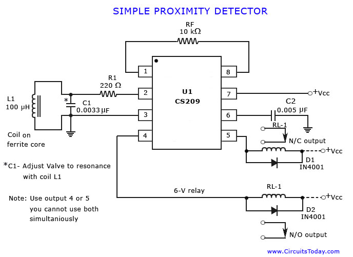
Proximity Detector Or Sensor
Magnetic Proximity Switch Circuit Diagram Available

Diy Magic Mirror
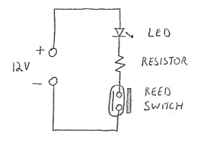
Magnetic Reed Dryreed Proximity Switch Sensor Circuit Diagram

Sm 9203 Proximity Sensor Wiring Diagram On Magnetic Sensor

Sr 4190 Proximity Switch Wiring Schematic Free Diagram

Mm model number range mm mounting electrical output switching frequency barrel material cable jacket size dwg.
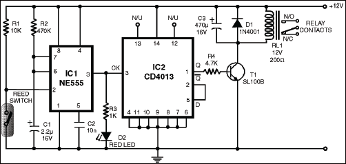
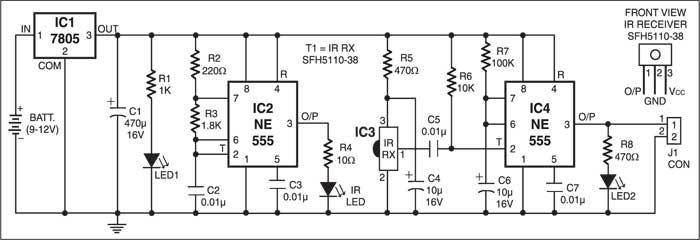
Mag ic proximity switch wiring diagram. Either the load is connected to negative and the positive is switched pnp continue reading an easy way to remember pnp and npn sensor. 3 wire and 4 wire dc inductive proximity sensors 3 wire and 4 wire dc 89 2 meter cable models dia. When a magnet is reached in proximity of s1 it closes to give a negative trigger at pin 2 of ic1 the output of ic1 goes high for a time determines by r2 and c2 this clocks the ic2 wired as. The schematic diagram symbol for a proximity switch with mechanical contacts is the same as for a mechanical limit switch except the switch symbol is enclosed by a diamond shape indicating a powered active device.
Here s a simple way remember how to wire up a 3 wire dc pnp or npn sensor. 3 khz ss pur 22 awg 1 nbb2 12gm50 e0 2 flush npn n o. Two three or four wire proximity sensors contain a transistor oscillator and a. Many proximity switches though do not provide dry contact outputs.
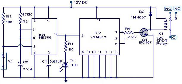
12 nj2 12gm40 e2 2 flush pnp n o. 1 5 khz ni brass pvc 26 awg 2. Wiring diagrams show the hook up offour sensors with npn and pnp outputs. As a consequence its output at pin 3 goes high for a short duration and supplies clock to the clock input pin 3 of ic2 cd4013 dual d type.
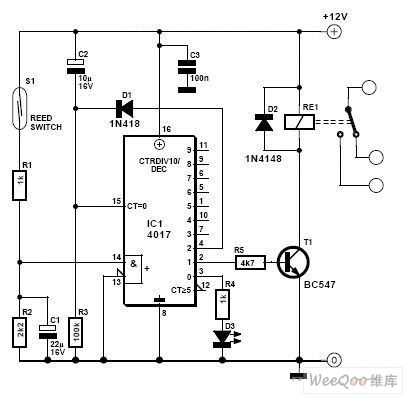
A monostable multivibrator based on ne555 ic1 and a toggle flip flop based on cd4013 ic2 does the rest of the circuit. H ere is the circuit diagram of a magnetic proximity switch that finds a lot of applications in many fields the circuit is based on a magnetic reed switch s1 as the proximity sensor. Magnetic proximity switch circuit. Diagram 4 figure 3 mmw ap 1h 54 00 mmw an 1h 54 00 npn diagram 3 mmw cp 1h 54 00 nc pnp diagram 5 18 mm diameter mafk1 a0 1h 53 00 0 to 70 mm 0 to 2 756 in flush no pnp m12 connector diagram 4 figure 4 mkw ap 1h 57 00 diagram 4 mkw an 1h 57 00 npn diagram 3 mkw cp 1h 57 00 nc pnp diagram 5 m series cylindrical magnetic proximity.
3 wire and 4 wire dc.
Magnetic Circuit Sensors Detectors Circuits Next Gr
Wiring Proximity Sensors To Parallel Port Inputs Electrical
Infrared Proximity Detector Circuit Detailed Circuit Diagram

Pin On Transmitters

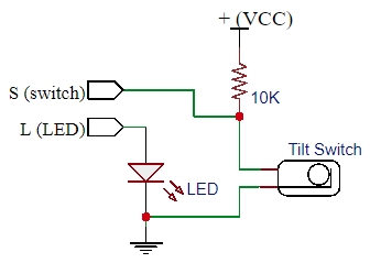
Simple Proximity Sensor Circuit And Working Circuitos

How To Wire A Proximity Sensor To A Plc Sensor Rockwell

Mag Ic Reed Switch Wiring Diagram Tuli Giant Slotenmaker
Magnetic Reed Switch Wiring Diagram H1 Wiring Diagram

Pin On Coding
Kr 3735 Mag Door Wiring Diagram Schematic Wiring
Magic Light Cup Module 2 Pack Protosupplies
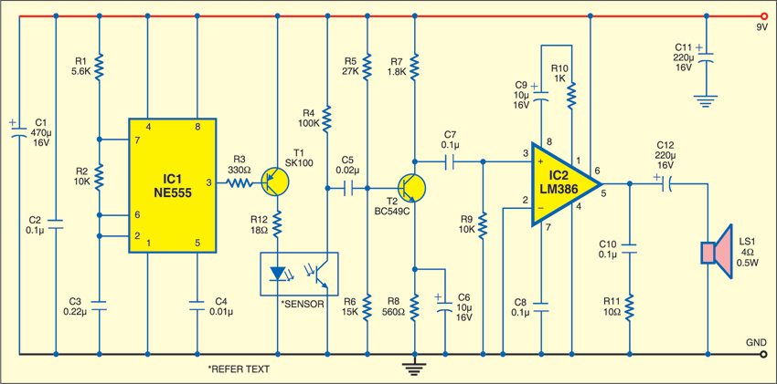
Ir Proximity Detector Detailed Circuit Diagram Available
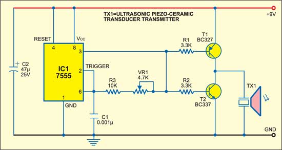
Ultrasonic Proximity Detector Detailed Circuit Diagram Available
