Mallory Unilite Wiring Diagram For Motorcycle

Mallory Promaster Coil And Distributor Wiring Diagram Unilite H1

Mallory Unilite Wiring Diagram Sbc Diagrams Schematics Inside
Mallory Ballast Resistor Wiring Diagrams Wiring Diagrams

Mallory Unilite Wiring Diagram For Motorcycle Wiring Diagrams
Points Distributor Wiring Diagram H1 Wiring Diagram

Msd Ignition Wiring Diagram Diagrams Schematics With Mallory
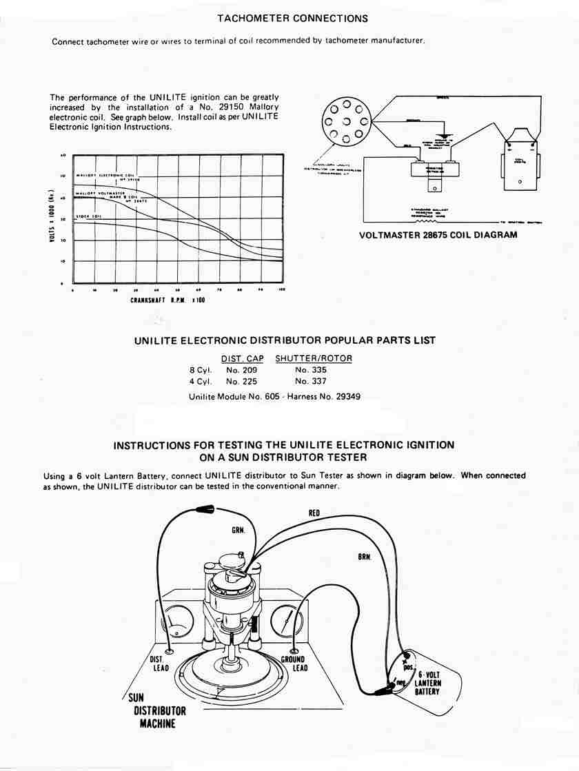
Plus a word of warning for anyone using the new sunpro 60 s style tachs.
Mallory unilite wiring diagram for motorcycle. These distributors are compatible with both kick start and electric start applications and can be installed without any engine disassembly when used with stock cylinders and heads. The easy three wire hookup of the unilite makes running a stock coil a mallory performance coil and even a mallory hyfire cd ignition a snap. Unilite distributor vacuum chamber and the carburetor. Unilite distributor for.
Vance does not rotate freely remove the unilite fi plate and find the source of the interference before proceeding. It shows the components of the circuit as streamlined forms as well as the power and also signal links between the tools. Now that you mention it. Installation procedure and diagrams are supplied with these adapters.
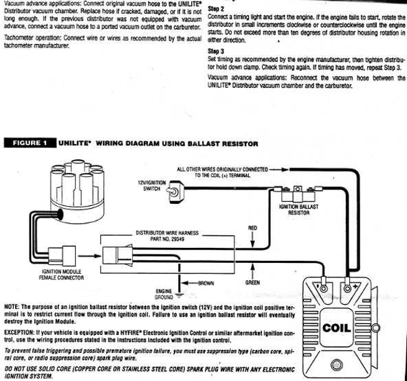
The a556 utilizes a stock style mechanical advance unit combined with our rugged e spark optical module and billet shutter wheel. Rotating the unilite plate. Collection of mallory ignition wiring diagram. The purpose of an ignition ballast resistor between the ignition switch 12v and the ignition coil positive terminal is to restrict current flow through the ignition coil.
A wiring diagram is a simplified standard pictorial depiction of an electrical circuit. Spark plug wires you must use suppression type carbon core spiral core suppression core spark plug wire. Loosen the two mallory 8 32 sleeve nuts to rotate the unilite fi plate and adjust the timing. 10 start the three wires of the mallory unilite module through the hole in the nose 14 route the wires from the unilite module to the ignition coil carefully 16 follow a factory shop manual to set the timing for your particular engine wiring diagram for mallory distributer don t worry if your coil doesn t look like this american one or.
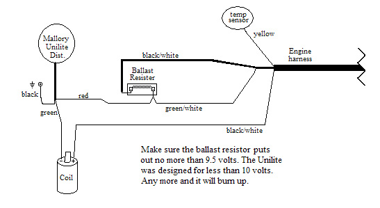
Wire attaches to the coil. 29349 ignition ballast resistor brown green red. Supplied with a quality cap and rotor the mallory unilite also provides a fully adjustable mechanical advance to dial in the perfect timing curve for a multitude of engine. Figure 1 unilite wiring diagram using ballast resistor coil ignition module female connector engine ground all other wires originally connected to the coil terminal distributor wire harness part no.
Unilite distributor vacuum chamber and the carburetor. The gauge light does have it s own ground wire because it has a plastic light socket. To do this the red lead from the voltmeter will go to the green wire on the coil. Make sure that the electrical posts on the back of the tach don t short out on the tach cup.
Must use carbon core spark plug wires do not use copper core. Mallory electronic ignition unilite. Also mallory sells a surge protector for unilites now. A legend returns the tried and true mallory unilite distributor line is back.
Mallory Hei Distributor Wiring Diagram Wiring Diagram Images

Mallory Distributor Wiring Diagram Diagram Red Bedding Wire
Mallory Tach Wiring H1 Wiring Diagram
Wiring Diagram For Ignition System H1 Wiring Diagram

Accel Hei Distributor Wiring Diagram 1 Automotive Mechanic

Image Result For Gm Hei Distributor External Coil Circuit Body

Chopcult 81 Yamaha Xj 650 Wiring Help Needed Motorcycle

Gm 4 Pin Hei Electronic Ignition Control Module Wiring Connections

Msd Digital 6 Wiring Diagram Valid Msd Hei Distributor Wiring

Gm Hei Distributor And Coil Wiring Diagram Yahoo Search Results

Alternator Wiring Dia Alternator Car Alternator Automotive

Https Encrypted Tbn0 Gstatic Com Images Q Tbn 3aand9gctwo6 Ddznezdbvwp9xkjd9zjdyfnrkudgbga Usqp Cau

Wiring Diagram 4 Pin Relay Fitfathers Me Fancy At Relay Wiring
