3a Universal Touch Switch Wiring Diagram

Optional switch mounting cases may be used to provide a stock look.
3a universal touch switch wiring diagram. 3a universal touch switch installation w led s duration. Draw a wiring schematic. Because the electrical code as of the 2011 nec update requires a neutral wire in most new switch boxes a 3 wire cable runs between the light and switch. This is an updated version of the first arrangement.
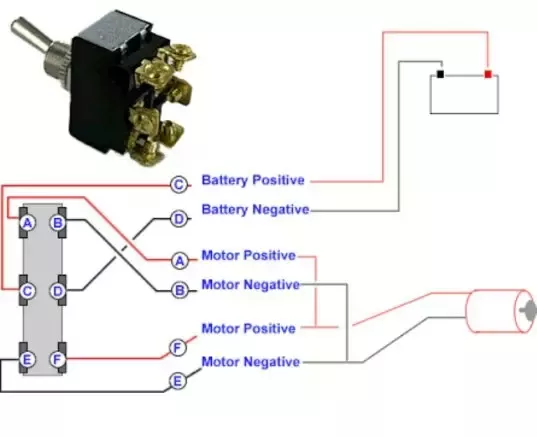
So given this information here is the wiring diagram for connecting the new unit. Black wire power or hot wire white wire neutral bare copper ground. 3a universal touch switch wiring diagram with the voltage tester still on touch the touch switch 1 of 3 dimmer for led lights panel home 3a racing universal. Below is the schematic diagram of the wiring for connecting a dpdt toggle switch.
There are different type modules you can buy such as 3 way or 2 way. November 18th choose your first switch and wire the positive side. These replacement modules have wiring diagrams with them. Plan each circuit carefully and include circuit protection either inline fuses or a fuse panel in the diagram.
I got a new 3 way touch sensor switch for my touch lamp. Connect wires to the motor assembly. Mount the switches in an appropriate place on door panel. I finally show and explain the wiring for the 3a universal touch switch from my previous video.
3a universal touch switch wiring explained duration. Use provided wire extension if needed. Worried i may have gotten the two white wires switched but i don t. The old sensor has the black red white and yellow wires.
Wiring a touch module in your lamp will enable you to transform your old lamp into something new and different. So it took a few e mails back and forth with pamela but she now has the lamp back up and running like new. This simple diagram below will give you a better understanding of what this circuit is accomplishing. Nathan burgun 8 700 views.
This is critical for a successful job. 3a racing universal touch switch wiring diagram. For more information contact your autoloc sales rep. Shown in diagram d matching the wire colors with the corresponding female plug.
The switch positions are acc for accessory r for run s for start and off for off. Please be sure to compare these general steps with your wiring diagram that was included with your touch. After reviewing the video i worried i may have gotten the two white wires switched but i don t. The back of the switch is marked with the function of the switch.
Terminals 3 and 4 represent the toggle switch. We will now go over the wiring diagram of a dpdt toggle switch. When wiring a 2 way switch circuit all we want to do is to control the black wire hot wire to turn on and off the load.

